
-min")
Table of Contents
1. Introduction
Tension test on steel rod is the type of test that is used to assess the properties of mild steel, tore steel, and high tensile steel under tension.
The primary objective of the tension test on the steel rod is to evaluate the properties of steel such as ultimate strength, percentage elongation, and Young’s modulus.
The test includes the process of subjecting a steel rod to tension load employing a Universal Testing Machine (UTM).
2. Principle of Tension Test on Steel Rod
The main principle of the tensile test is based on exposing the given specimen to tensile load followed by marking of extension against the load within the elastic limit.
Subsequently, the load values at the yield point, breaking point, and the ultimate point are recorded.
Using these values, the stress-strain graph is duly plotted.
3. General Test Procedure of Tension Test on Steel Rod
The general test procedure of the tension test on steel rods has been briefly described below.
Objective
To evaluate the properties of steel rods namely Young’s modulus, Ultimate Strength and Percentage Elongation.
Apparatus Required
a. Universal Testing Machine (UTM):
The universal testing machine consists of two important units i.e. the loading unit and the control panel which is briefly described as follows:
i. Loading Unit:
As the name itself implies, the loading unit is the part of UTM that is designed for the loading of the specimen.
This unit consists of three crossheads i.e. upper head, middle head, and lower head.
The respective crossheads are used depending upon the nature of the load namely tensile load, compressive load, and shear load.
In this test, the upper and lower crossheads are used.
ii. Control Panel:
The control panel is the unit of UTM that facilitates and aids the process of load application on the specimen.
It consists of a pendulum dynamometer to measure the force exerted by the specimen.
The load application is completed by the application of hydraulic pressure.
A load indicating dial is also mounted at the side of the control panel.
d. Punching Tools
e. Vernier Callipers
f. Extensometer
Procedures
The procedure for conducting the tension test on steel rod consists of the following series of steps:

1. First of all, the specimen is thoroughly cleaned and the gauge length is marked on the steel rod using the punching tool.
The formula for the calculation of gauge length is ![]() .
.
2. The next step includes the calculation of range. Generally, a suitable value for the tensile stress is assumed and the maximum expected load capacity is computed.
Using this, the range is calculated and is duly set in the universal testing machine. For example, lets us assume the working stress as 140N/mm².
Taking factor of safety as 3, the ultimate stress is obtained as,
Ultimate Stress = 140 * 3 = 420 N/mm²
Using the computed value of ultimate stress, the range is set.
3. The specimen is then placed on the testing machine by operating the handle in such a way that the specimen firmly fits at the base.
The right valve is kept in an open position while the left valve is kept in a closed position.
The pointer is adjusted to zero utilizing the adjusting knobs.
The specimen is gripped firmly and after the placing of the specimen, the jaws are locked.
4. The extensometer is then fixed on the specimen and the reading is set to zero.
5. The load is then applied to utilize the right valve.
The release of the loaded specimen is done using the left valve.
6. The loading rate is increased gradually until the pointer moves backward and the specimen finally breaks.
The load just before such breaking is known as the ultimate load and the load at the instant of breaking is known as the breaking load.
7. The change in length can be obtained from the extensometer reading.
8. Stress at different values of strain is computed from the following formula and the graph is plotted.
Stress = Load/ Area
Calculations
Following calculations are made after recording the values:
Modulus of Elasticity = Stress (within elastic limit) / Strain
Yield Stress = ( Load at yield point / original c/s area)
Normal Wreaking Stress = Breaking load / Nominal breaking stress
Actual Breaking Stress = Breaking Load / Neck area
Percentage Elongation = (Change in length / Original Length) * 100
Percentage Reduction in Area = (Change in length / Original Length) * 100
After the calculation; the graph is plotted between stress and strain using the calculated data.
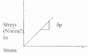
Fig.4.Stress-Strain Graph for Tension Test on Steel Rod
Result
The following result is obtained after the lab experiment on the steel rod.
1. Young’s Modulus ……………. (N/mm2)
2. Yield Stress ……………. (N/mm2)
3. Ultimate Stress ……………. (N/mm2)
4. Normal Breaking Stress …………….. (N/mm2)
5. Actual Breaking Stress ……………. (N/mm2)
6. % Elongation ……………… %
7. % Reduction for area ……………….%
| Read Also: Vane Shear Test |