Table of Contents
1. Introduction
There is a certain working pressure of pipes and this limit should not be crossed. Due to water flowing in the pipe, hydrostatic pressure is exerted on the joints and fittings of the pipe. If this pressure exceeds the allowable working pressure of the pipe, it may burst. So, to break the hydrostatic pressure, a tank is specially built which is known as a break pressure tank.
It is also abbreviated as BPT.
A break pressure tank is also referred to as a break pressure chamber.

In this tank, water is permitted to discharge freely in the atmosphere which reduces the hydrostatic pressure to zero.
Storage tank, sedimentation tank, collection chamber, distribution chamber, etc act as a break pressure tank.
Break pressure tank is generally constructed of stone masonry, RCC, Ferro cement, etc.
It is usually located downstream i.e. between the water reservoir and water supply points.
2. Mostly Used Region – Break Pressure Tank
In hilly or high altitude regions, water supply is generally done by the gravity method. There is no control of pressure in pipelines.
Due to the high gradient, the velocity of water is also very high. So, Break Pressure Tanks are built at suitable distances to reduce the hydrostatic pressure in the pipe.
3. Types of Break Pressure Tank
There are 3 types of break pressure tanks based on the slope of the pipeline. They are:
a. Average slope of the pipeline is greater than the slope of the energy gradient

~ Hydraulic gradient line will be below the average slope of the pipeline.
~ Frictional losses will be always less than the static height at full flow condition.
~ In addition to the above pipeline alignment, No water will remain in the pipeline at the no-flow condition.
b. Average slope of the pipeline is less than the slope of the energy gradient line

~ Hydraulic gradient line will be above the average slope of the pipeline.
~ Frictional losses will be more than static height at full flow condition.
~ No water will remain in the pipeline at no flow condition as similar to the first one.
c. Average slope of the pipeline is less than the slope of energy gradient line, but pipeline having a decreasing slope and then increasing (like inverted siphon)

~ Hydraulic gradient line will be above the average slope of the pipeline.
~ Water will remain in the pipeline at the no-flow condition.
4. Application of Break Pressure Tank
1. It is constructed in an area where the flow of water in the pipeline is high and which may cause bursting of pipe.
2. It is used in the high-altitude or hilly areas where the gravity system is commonly used to distribute water.
5. Construction of Break Pressure Tank
a. Planning and Site Selection:
In planning, observations and calculations are done to find out the high-pressure points in the pipeline and also to determine the number of break pressure tanks needed in order to reticulate the water supply system.
The number of break pressure tanks required at what distance is also found out and cost estimation is done to check whether the expenditures meet the budget or not.
BPT is mostly constructed in high-altitude areas. So, the site should be selected based on the availability of materials for construction & the economy of construction.
b. Construction:
After planning and selecting the site, now turn to construct the BPT.
Mostly the BPT is constructed downstream.
It is generally constructed of stone masonry, RCC, Ferro cement, etc.
BPT is a rectangular tank structure having a base of 1000mm * 1000mm and a height of 1200mm.
It also includes a lockable lid at the top that controls access into the interior of the BPT, so that it can be easily maintained from time to time whenever required.
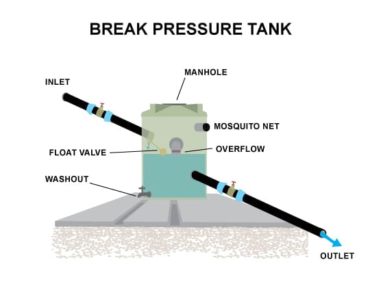
Break pressure tank includes:
i. Inlet pipe:
It is the pipe through which the water enters into the BPT with high pressure. It is situated at the top end of the tank.
ii. Outlet pipe:
It is the pipe through which the water exits from the BPT with medium pressure to the water supply points. It is situated at the lower end of the tank.
iii. Perforated pipe segment:
The pipe arrangement includes the perforated pipe segment which is located within the tank structure near the bottom end and upstream of the outlet end.
iv. Control valve:
It is located between the inlet end of the pipe and the perforated pipe segment within the tank structures. The main purpose of the control valve is to control the flow rate of water through the flow line.
v. Float actuated operating mechanism:
It is located between a fully open and closed position for displacing closure members of the control valve.
| Read More: Water Distribution System |
| Read More: Water Treatment Process |

