
Table of Contents
Several soil tests for road construction must be carried out before the commencement of the road construction work to understand the nature and properties of soil. Also, for any road construction, it is necessary to determine the soil profile.
Soil tests are necessary to plan and design the proposed structure being constructed.
Soil can be regarded as the structural basis of any construction work as most structures are erected on the soil. In this regard, soil can be considered the foundation of all types of surface construction, including roads.
Soil should have an acceptable quality to ensure adequate structural strength and safety. Thus, soil testing is the first step in any construction work, particularly road construction.
1. Purposes of Soil Tests for Road Construction
a. To analyze the quality of the soil.
b. To determine the moisture present in the soil.
c. To determine the compaction characteristic of various soil.
d. To find out the strength of the subgrade.
e. To determine the nature of the soil.
2. Soil Tests for Road Construction
The soil tests that must be carried out for road construction are briefly explained as follows:
a. Moisture Content Test
The moisture content of the soil is the amount of water it contains and is expressed as the percentage of dry mass.
The test for determining the moisture content of the soil is vital for assessing the existing natural state of the soil.
It is also necessary to understand the bearing capacity and the probable settlement of the soil.
It is carried out in the laboratory itself.
Apparatus Required:
1. Non-corrodible airtight container
2. Weighing Balance of adequate sensitivity
3. Desiccator
4. Oven
Procedure:
The procedure for laboratory determination of moisture content can be listed as follows:
i. The air-tight container along with its lid must be first weighed(W1).
ii. The specimen sample is then taken in the container, and the container, along with its lid and the sample, is weighed(W2).
iii. Then, the container is left in the oven. The specimen is dried to a constant weight at a temperature ranging from 105 degrees Celsius to 110 degrees Celsius for about 16 to 24 hours.
iv. The container, lid, and dried sample are finally weighed(W3).
v. The moisture content is then calculated using the following formula:
W= [ (W2-W3) / (W3-W1) ] * 100
Where,
W1= Weight of the container with a lid in grams
W2= Weight of the container with lid and wet sample in grams
W3= Weight of the container with lid and dry sample in grams
b. Specific Gravity Test By Pycnometer Method
The specific gravity of soil may be defined as the ratio of the mass of solids to the mass of an equivalent volume of water at 4ºC.
Mathematically,
G = Ms / Mw = ρs / ρw = γs / γw
Where,
ρs = Density of Solid
ρw = Density of Water
γs = Unit Weight of Solid
γw = Unit Weight of Water
A specific gravity test is necessary to understand various soil properties such as void ratio, degree of saturation, etc.
Pycnometer Method
A pycnometer or constant volume method is most reliable for determining specific gravity. Normally about 200 gm of the dry mass of the sample and 500 cc. Constant volume bottles are taken.
Apparatus Required:
1. Pycnometer

Fig: Pycnometer
2. Weighing Balance with a weighing accuracy of 1gm
Procedure:
The laboratory procedure for determining the specific gravity of soil by pycnometer method can be listed as follows:
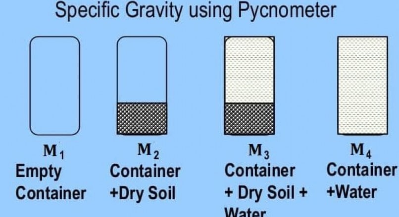
1. Find the mass of the empty pycnometer, say M1.
2. Fill pycnometer with about 200 gm of dry sample and take its weight, say M2.
3. Add water to the pycnometer such that it is half full of water. The air in the soil sample is completely expelled by heating or suction.
Then the water is added to its full capacity, and the pycnometer is weighed and say M3
4. Empty the pycnometer of all its contents and clean it. Next, the pycnometer is filled with water only, and its weight is determined say M4.
Calculation:
G = [M2-M1] / [ (M2-M1) – (M3-M4)]
Where,
G = Specific Gravity
M1 = Mass of empty container
M2 = Mass of Container + Dry Soil
M3 = Mass of Container + Dry Soil + Water
M4 = Mass of Container + Water
| Read Also: Types of Pipes in Civil Engineering & Construction |
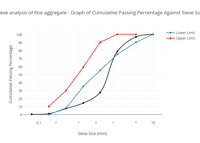
c. Particle Size Distribution Test
The particle size distribution of soil may be defined as the proportion of the dry mass of soil distributed over specified particle-size ranges, i.e., gradation of soil.
Determining particle size distribution is necessary to check the soil’s suitability for use in road construction.
This test aims to determine the percentages of different grain sizes contained in the soil.
Normally sieve analysis is used for determining the particle distribution for larger particles, and a hydrometer test is used for the finer ones.
Sieve Analysis For Particle Distribution
Apparatus Required:
1. Weighing Balance
2. Set of sieves
3. Cleaning brush
4. Sieve shaker
Procedure:
The procedure for sieve analysis involves the following series of steps:
1. A sample of about 500 grams is first taken.
2. The representative sample is dried in a ventilated oven.
3. If the sample consists of lumped particles, the lumps must be crushed.
4. The sample is weighed, and its mass is duly recorded.
5. The sieves of different sizes are then taken and arranged in a particular order, i.e., the largest aperture size at the top and the smallest at the bottom. A pan is placed at the bottom to collect the samples.
6. The weighed sample is poured into the top of the stack of sieves, and the lid is put.
7. The stack of sieves is stacked in the sieve shaker, and the clamps are fixed.
8. The timer is set to 10 or 15 minutes, and the sieve shaker is switched on.
9. Afterwards, the sample retained on each sieve is weighed.
10. The result is then calculated using the following formula:
% Retained = (W sieve /W total ) * 100%
Where,
W sieve = mass of aggregate in the sieve
W total = total mass of aggregate
% cumulative passing = 100% – % cumulative retained
The values are then plotted on the graph with the sieve size on X-axis and the
cumulative % passing on the Y-axis.
d. Proctor Test
The Proctor test is a type of compaction test carried out to determine the compaction properties of soil.
In actuality, this test is used for determining the mass of dry soil per cubic meter when the soil is compacted over a range of moisture contents providing the maximum dry density at the optimum moisture content.
Proctor test includes establishing the relationship between the moisture content and dry density of soils compacted in a mold of a specific size with a 2.5kg rammer dropped from a height of 30cm.
There are two methods of Proctor Tests.
a. Standard Proctor Test ( AASHO Test)
b. Modified Proctor Test ( Modified AASHO Test )
a. Standard Proctor Test ( AASHO Test)
R.R. Proctor developed Standard Proctor Test. This test is used to determine the optimum moisture content for the soil under given compaction.
Apparatus Required
a. Standard Proctor Apparatus
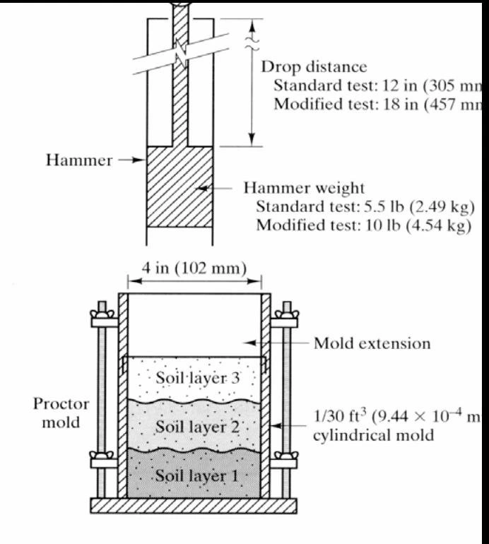
i. Cylindrical metal mold of an internal diameter of 4 inches ( 102 mm ) and effective height of 4.6 inches ( 117 mm ) with an internal volume of 1/30 cu. ft ( 0.945 ltr ).
ii. A 50 mm diameter rammer of weight 2.5 kg and height of fall of 1 foot ( 305 mm ), moving in the metallic outer sleeve.
iii. Detachable collar of 50 mm effective height ( 60 mm total height ).
iv. Detachable base plate
b. Thermostatically controlled oven (105°C +- 110°C)
c. Mixing Tools like a spoon, trowel, and spatula.
d. Tray & scoop
e. Containers
Procedure
i. About 3 kg of air-dried and pulverized soil passing through a 4.75 mm sieve is taken in a tray.
ii. The quantity of water added for the first trial is computed. The computed quantity of water is added to the soil in the tray and mixed thoroughly by hand to ensure uniform water distribution.
iii. The mold is cleaned and dried, and the weight of the empty mold with the base plate but without a collar is taken ( say M1 ). The collar is then attached to the mold.
iv. The mold is filled with wet soil taken from a tray in 3 equal layers and compacted each layer with 25 uniformly distributed blows on the surface using a standard rammer.
v. The collar is removed, and extra soil is trimmed off to make it level with the top of the mold.
vi. The mold weight with base plate and compacted soil is taken ( say M2 ).
vii. Knowing the mass of compacted soil ( M2-M1 ), bulk density(ρ) is calculated.
i.e. Bulk Density(ρ) = M / V = (M2-M1) / V
Where V = Volume of soil (the same as the volume of the mold).
viii. A representative sample of compacted soil is taken from the middle of the mold, and its water content is determined. It is best to take 3 or more samples to determine water content.
The dry density of the soil is obtained as :
ρdry = ρ / (1+W)
ix. Several such tests are conducted with soil samples having different moisture content and ρdry workout for all the tests.
x. A graph is plotted between dry density and water content to obtain a compaction curve.

xi. The optimum moisture content and the corresponding maximum dry density are determined from the graph.
Observations & Calculations:
Dia. of the mold =
Mould Height =
Mould Volume, V=
The specific gravity of soil, G=
| Sl. No. | Observations and Calculations | Determination No. | ||
| 1 | 2 | 3 | ||
| Observation | ||||
| 1 | Mass of empty mold with base plate | |||
| 2 | Mass of mold compacted soil and base plate | |||
| Calculations | ||||
| 3 | Mass of compacted soil M = (2) – (1) | |||
| 4 | Bulk Density | |||
| 5 | Water content, w | |||
| 6 | Dry density | |||
| 7 | Void ratio | |||
| 8 | Dry density at 100% saturation (theoretical) | |||
| 9 | Degree of saturation | |||
Result:
Maximum dry density (from the plot) =
Optimum water content (from the plot) =
b. Modified Proctor Test ( Modified AASHO Test )
The modified proctor test was developed to give higher standard compaction with the advent of heavy vehicles and the need for higher compaction.
As this test was standardized by the American Association of State Highway Officials, it is also known as the modified AASHO test.
The test procedure is similar to a standard proctor test, except for applying higher compactive effort. The mold used is the same as in the standard proctor test ( proctor mold of capacity 1/30 cu. ft. or 0.945 ltr). But the soil compacted into 5 layers giving 25 blows to each layer, with a rammer of 10 lb (4.54 kg) and height of fall of 18 inches ( 45.72 cm ).
The dry densities are obtained for different water contents by adopting a similar procedure as in the standard proctor test, and the compaction curve is drawn.
Since the compactive effort is more for this test than for a standard proctor test, the compaction curve for the modified proctor lies higher.
The heavier compaction increases the maximum dry density but decreases the optimum moisture content.
e. California Bearing Ratio Test
California Bearing Ratio Test is carried out to check the strength of the subgrade of pavement.
By comparing the results of this test with a set of standard curves or values, the thickness of the subsequent layers can also be determined.
It is a type of penetration test and is extensively used in the design of flexible pavements. This test was developed by the California Division of Highways of the United States.
California Bearing Ratio is the ratio of force per unit area required to penetrate a soil mass with a piston of 1.25mm/min corresponding to that required for the penetration of a standard material.
CBR = ( Test load / Standard load ) * 100
Apparatus Required:

a. Steel: Cutting Collar
b. Dial Gauges
c. Weighs
d. IS Sieves
e. Penetration Plunger ( Diameter: 50 mm & Height: 100 mm )
f. Spacer Disc ( Diameter: 148 mm & Height: 47.7 mm )
g. Loading Machine
h. Cylindrical Mould ( Diameter: 150 mm & Height: 175 mm )
i. Rammers
California Bearing Ratio Test Procedure:
The procedure for conducting the CBR test is as follows:
1. Prepare the soil sample passing through a 20 mm IS sieve but retained on a 4.75 mm IS sieve.
3. About 4.5kg to 5.5 kg of the sample is mixed with water ( commonly distilled water ). A spacer disc is placed over the base plate, and coarse filter paper is placed over the spacer disc. Then internal oiling of the mold is done, and the mold is fixed in its position. At the top of the mold, a collar is placed.
4. The soil mix is compacted in several layers by static or dynamic compaction.
For Static Compaction: Compacting soil in loading machine ( gradually increasing load ).
For Dynamic Compaction: Compacting soil by rammer ( impact load ).
For light compaction, the soil is compacted into 3 layers by 56 blows with a 2.6 kg rammer from a height of 31 cm.
For heavy compaction, the soil is compacted into 5 layers by 56 blows with a 4.89 kg rammer from a height of 45 cm.
| Light Compaction | Heavy Compaction | |
| No. of layers | 3 | 5 |
| Rammer Weight | 2.6 kg | 4.89 kg |
| Fall | 31 cm | 45 cm |
| Blows | 56 | 56 |
5. The collar is then removed, and the soil is trimmed. The mold is then turned over, and the base plate and spacer disc are removed.
6. The mold is then weighed and bulk density, as well as dry density, is determined.
7. Then, the mold and the surcharge weight are placed on the penetration test machine.
8. The load is applied to the piston such that the rate of penetration is 1.25mm/min.
9. The load readings at penetrations of 0.5,1.0,2.0,2.5,3.0,4.0,5.0,7.5,10 and 12.5 mm are recorded.
10. The mold is detached from the loading equipment, and moisture content is determined.
Standard Load Values for California Bearing Ratio Test:
| Penetration(mm) | Standard Load(kg) | Unit Standard Load(kg/cm2) |
| 2.5 | 1370 | 70 |
| 5 | 2055 | 105 |
| 7.5 | 2630 | 134 |
| 10.0 | 3180 | 162 |
| 12.5 | 3600 | 183 |
Observations During California Bearing Ratio Test:
Weight of soil taken =
Weight of surcharge =
Area of the plunger, A =
| Sl No. | Penetration (mm) | Proving dial reading | Load on plunger (kg) | Corrected load | Unit Load |
Result of California Bearing Ratio Test:
California Bearing Ratio at 2.5mm penetration =
California Bearing Ratio at 5.0mm penetration =
California Bearing Ratio of subgrade soil =
f. Core Cutter Method
Determining dry density by the core cutter method generally involves hammering or jacking a steel cylinder ( with known mass and volume) into the soil, thereby determining the mass of the soil.
This method is used for dry density determination.
This method is not desirable for coarse-grained soil or coarse-grained pavement materials.
Apparatus Required:
1. A steel rammer of mass of 9kg and the overall length, including the foot and staff, of about 900mm.
2. A cylindrical core cutter with 100mm internal diameter and 130mm long.
3. Weighing balance with an accuracy of 1 gram.
4. Steel dolly with 100mm internal diameter and 25mm high.
5. Palette knife.
6. Straight edge, ruler of steel, etc.
Procedure:
The procedure for the dry density determination by the core cutter method involves the following series of steps:
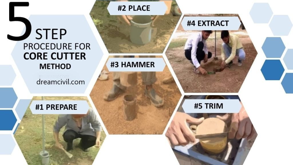
i. The experimental setup of the cylindrical core cutter is first made.
ii. The steel dolly is placed over the cutter to prevent damage to the edges of the core cutter.
iii. The cylinder is then embedded into the ground up to its full height with the help of a rammer and is taken out by excavating its sides without disturbing the sample.
iv. The surplus soil at both ends is trimmed, and the weight of the cylinder with soil is determined.
v. Then, volume is determined from the cutter’s known dimension.
vi. Moisture content of the soil is determined with the oven drying method.
vii. The dry density of the soil is then computed using the following formula:
Bulk Density (γ t ) = (W 2 – W 1 ) / V
Dry Density (γ d ) = γ t / ( 1 + W)
Where,
W 1 = Weight of cutter
W 2 = Weight of the soil + cutter
W 2 – W 1 = Weight of soil
V = Volume of the cutter
Observation and Calculations:
| Sl. No. | Observations and Calculations | Determination No. | ||
| 1 | 2 | 3 | ||
| Observations | ||||
| 1 | Core cutter No. | |||
| 2 | Internal diameter | |||
| 3 | Internal height | |||
| 4 | Mass of empty core cutter (M1) | |||
| 5 | Mass of core cutter with soils (M2) | |||
| Calculations | ||||
| 6 | M=M2 – M1 | |||
| 7 | The volume of cutter V | |||
| 8 | Water content | |||
| 9 | Dry density using formula | |||
Results of Core Cutter Method:
Dry density of the soil= ________g/ml.
| Read Also: Los Angeles Abrasion Test |
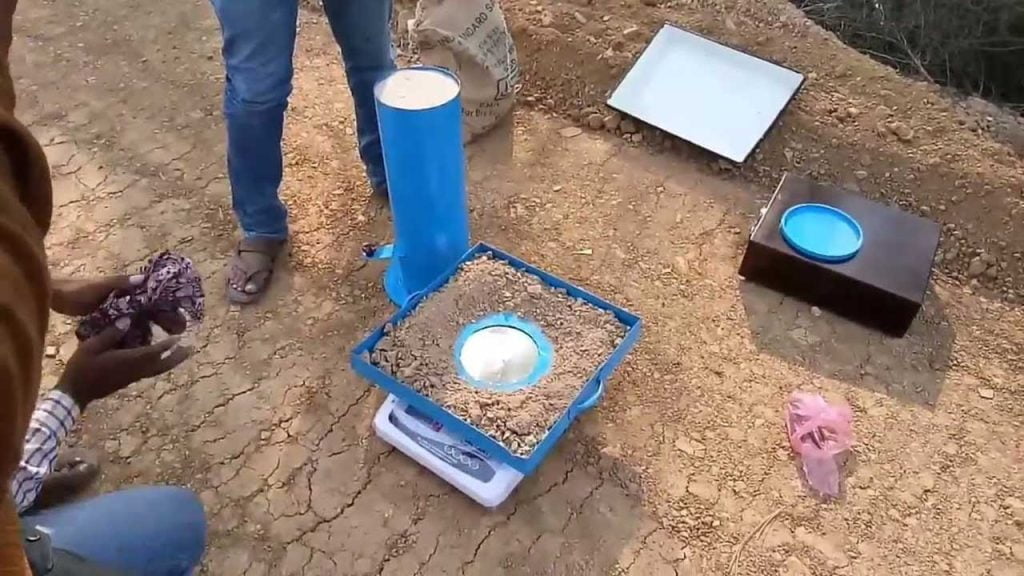
g. Sand Replacement Method
Usually, the soil after compaction in the field has to be checked for the specified dry density. This is usually done by the sand replacement method.
This method is also commonly known as the Sand Cone Method.
The determination of dry density is of utmost importance as it is required for the estimation of the bearing capacity of the soil.
Furthermore, it is also used for assessing the pressure on underlying strata of soil, settlement of the soil as well as the stability of the soil layer.
This method is highly suitable for cohesionless soil.
The general test procedure for determining the dry density of soil by the sand replacement method is relatively simple and easy to conduct.
The test can be carried out using a small or large cylinder. Commonly, it is conducted using a large cylinder.
The sand replacement test is mostly carried out at the ground or formation levels.
Apparatus:
1. Sand Cone Apparatus or Sand Pouring Cylinder.
2. Soil excavation and cutting equipment such as scrapers.
3. A plane surface such as a square glass plate with a thickness of 9mm or larger.
4. A metal container for the collection of the excavated soil.
5. A square metal tray about 40 mm deep with a hole of about 100mm in diameter at the center of the tray.
6. Weighing balance with an accuracy of up to 1 gram.
7. A ventilated oven.
Procedure:
The procedure for the determination of dry density by the sand replacement method involves the following series of steps:
i. Initially, the apparatus is set up as shown in the figure below.

ii. The square tray is then placed on the leveled ground.
iii. A small quantity of soil is then excavated from the hole.
iv. The excavated soil is duly weighed, and the water content of the excavated soil is determined.
v. The hole is then filled by the sand of known density from a sand bottle.
vi. Then, the weight of the sand filling the cone of the sand bottle is taken separately.
vii. The dry density is computed as follows:
Weight of sand filling the hole = W 2 – W 3 – W 4
Unit weight of sand = γ
Volume of sand = (W 2 – W 3 – W 4 ) / γ = Volume of hole (V)
Bulk density (γ t ) = W 1 / V
Thus,
Dry Density (γ d ) = γ t / ( 1 + W)
Where,
W 1 = Weight of soil in the hole
W 2 = Weight of the sand bottle before pouring
W 3 = Weight of sand bottle after pouring
W 4 = Weight of sand filling conical funnel
W = Water Content
3. Advantages of Soil Tests for Road Construction
a. It helps to finalize the requirement of soil for road construction.
b. It gives the knowledge about various properties of soil.
c. It helps to determine the moisture content present in the soil.
d. It helps to find out the strength of road or pavement subgrade.
e. It helps to analyze the quality of the soil.
f. Material requirements for road construction and the nature of the road can be easily determined.
g. It helps to predict the thickness of the road pavement.
i. It helps to determine the load-bearing capacity of the road.
| Read Also: Core Cutter Method |
| Read Also: Parapet Wall | Types of Parapet Wall | Construction & Codal Provision of Parapet Wall |