Table of Contents
The pump is known as a centrifugal pump if the mechanical energy is converted into hydraulic energy, utilizing centrifugal forces acting on the liquid.
✔ But if the mechanical energy is converted into hydraulic energy (or pressure energy) by the process of sucking the liquid on a cylinder in which a piston is reciprocating ( i.e., moving backward and Forwards ), which applies the thrust on the liquid and increases its hydraulics energy (Pressure Energy), the pump is known as Reciprocating Pump.
The pump which increases the hydraulic energy of the liquid by applying thrust is called the reciprocating pump.
1. Main Parts of Reciprocating
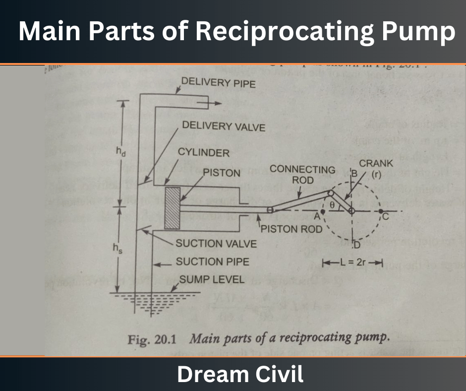
The following are the main parts of a Reciprocating pump, as shown in fig 1.

Fig: 1
a. A cylinder with a piston, piston rod, connecting rod, and crank.
b. Suction Pipe
c. Delivery Pipe
d. Suction Valve
e. Delivery Valve
2. Working of a Reciprocating Pump

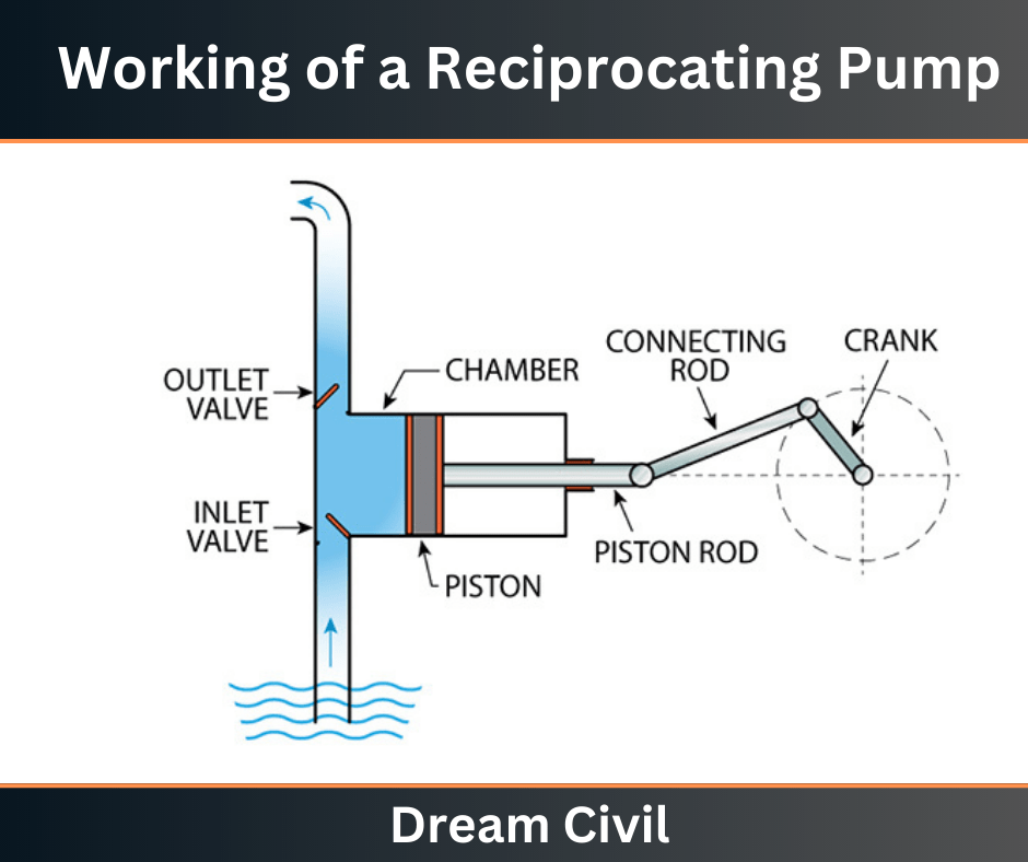
✔ Fig 1 shows a single-acting reciprocating pump, which consists of a piston that moves forward and backward in a closed fittings cylinder.
The movement of the piston is obtained by connecting the piston rod to the crank utilizing a connecting rod.
✔ The electric motor is used in this process to rotate the crank.
✔ The suction and delivery pipes with the suction valve and delivery valve are attached to the cylinder.
The suction and delivery valves are one-way or non-return valves, allowing the water to flow in one direction only.
The suction valve allows water from the suction pipe to the cylinder, while the delivery valve only allows water from the cylinder to the delivery pipe.
✔ When the crank starts rotating, the piston moves to and fro in the cylinder.
The piston is in the cylinder’s extreme left position when the crank is at A.
As the crank is rotating from A to C (i.e., from θ = 0° to θ = 180°), the piston is moving towards the right in the cylinder.
✔ The movement of the piston towards the right creates a parallel vacuum in the cylinder. But on the surface of the liquid in the sump, atmospheric pressure is deputy, which is greater than the pressure inside the cylinder.
Thus, the liquid is moved into the suction pipe from the sump. The liquids open the suction valve and center the cylinder.
When the crank is rotated from C to A ( i.e., From θ = 180° to θ = 360°), the piston from its extreme right position starts moving towards the left in the cylinder.
✔ The piston’s motion near the left raises the pressure of the liquid inside the cylinder greater than the atmospheric pressure.
Hence suction valves close, and the delivery valve opens. The liquid is forced into the delivery pipe and is raised to the required height.
Read More: Types of Pipes
2.1 Discharge through a Reciprocating Pump
Consider a single-acting reciprocating pump, as shown in fig below:

Let,
D = Diameter of the cylinder
A = Cross-sectional area of the piston or cylinder
r = Radius of Crank
N = r.p.m of the crank
L = Length of the crank
hs = Height of the cylinder’s axis from the water surface in the sump.
hd = Height of Delivery Outlet above the cylinder axis ( Called delivery head)
The volume of water delivered in one revolution or discharge of water in one revolution = Area x Length of stoke = A x L
Number of Revolutions per second, = N/60
Discharge of the pump per second,
Q = Discharge in one revolution x No. of revolution per second. = (A x L x N)/60 …….. (1)
Weight of water delivered per second, W= ρ x g xQ
W = (ρgALN)/60 ….. (2)
2.2 Work Done by Reciprocating Pump
Work done by the reciprocating pump per second is given by the reaction as,
Work done per second = Weight of water lifted per second x Total height through which water is lifted = W x (hs+hd)
Where,
(hs+hd) = Total height through which water is lifted,
From equation (2), weight W is given by,
W = (ρgALN)/60
Substituting the value of W in equation (1), we get
Work done per second = (ρgALN)x (hs+hd)/60
Power required to drive the pump, in KW
P= Work done per second/1000
P = (ρgALN)x(hs+hd)/60×1000
P = (ρgALN)x(hs+hd)/60000 KW
Read Also: Parapet Wall
3. Slip of Reciprocating
The slip of a Jump is defined as the difference between the theoretical discharge and the pump’s actual discharge.
The discharge of a single-acting pump is given by equation (1) as (A x L x N)/60 and of a double-acting pump is given as (2 x A x L x N)/60 are theoretical discharges. The actual discharge of a pump is least than the theoretical discharge due to leakage.
The difference between the theoretical and actual discharge is known as the slip of the pump. Hence Mathematically,
Slip = Qth-Qact
But slip is mostly expressed as percentage slip which is given by,
Percentage slip = ((Qth-Qact) / Qth) x 100%
( Qact / Qth = C )
= (1-Cd ) x 100
Where, Cd = Coefficient of Discharge
4. Classification of Reciprocating Pumps
The reciprocating pumps may be classified as,
1. According to the water being in contact with one side or both sides of the piston:
The pump is known as single-acting if the water is in contact with one side of the piston.
On the other hand, if the water is in contact with one side of the piston, the pump is called a Double-acting pump.
Hence classification according to the contact of water is,
a. Single-acting Pump
b. Double-acting Pump
2. According to the number of cylinders provided:
According to the number of cylinders provided, the pumps are classified as:
a. Single cylinder Pump
b. Double cylinder Pump
c. Triple Cylinder Pump
5. References1. Content Filter & Authenticity Checking Team, Dream Civil International (Our team checks every content & detail to maintain quality.) |
Read Also: Water Treatment Processes

