Table of Contents
Micro tunneling is an efficient trenchless method for making small-diameter tunnels.
The process helps spread pipelines under highways, railroads, and other sensitive zones with the lowest disturbance to businesses and traffic on the surface.
1. Micro Tunneling
It presents precise line and level installations with different ground requirements. The powerful usefulness of micro tunneling is in the field of sewerage, drinking water, and communication and power supply networks.
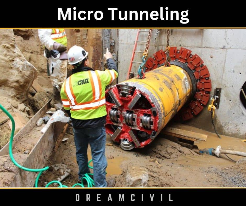
Because of the tiny diameter of these tunnels (roughly 500 mm to 4,000 mm in diameter), it is not suitable for an operator to move the tunneling machine; therefore, a remotely managed micro tunnel boring machine (MTBM) connected with the pipe jack-and-bore method is utilized for construction.
Pipe jacking possesses lining a tunnel bore designed by a shield or other means by pushing specially-designed jacking conduits into the tunnel bore from one shaft to another.

2. Microtunneling and Pipe Jacking System
A micro tunneling and pipe jacking system includes the following components:
1. MTBMs
It is a mechanized, steerable mini boring machine with a suitable front cutter head to excavate smaller diameter tunnels.
It utilizes a laser guidance system to send the operator real-time feedback and projected position. The operator employs a steering jack to steer the machine during drives.
2. Jacking System
It contains high-thrust hydraulic jacks mounted on a jacking frame qualified to exert the needed jacking force against a purpose-built thrust wall to force the pipes and the shield forward through the ground.
3. Automated Spoil Removal System
Discharge pumps maintain the slurry through the circuit to the separation plant and up to the vibrating screen, where the coarse material is filtered out and gathered in a container.
Pumps transport the screened suspension into cyclones, where the fine material is disconnected.
4. Guidance System
It possesses a laser beam device established on the jacking shaft, positioned to the preferred level, gradient, and alignment.
Some appliances hold photosensitive cells on the target panel at the shield’s rear to alter the laser part into digital data.
5. Remote-Control System
The remote-control system is employed to work the shield and other equipment.
It estimates, monitors, and records essential data while showing any defects on the monitor.
3. Planning Process for Micro tunneling
The planning stage of Micro tunneling contains soil/rock testing and gathering and representation of geotechnical information and data.
Depending on this, an applicable MTBM system and slurry-breaking equipment are fixed for the project.
The steps are described below:
a. Select the pipeline position and grade
To find the position of the pipeline, it is necessary to know the ground requirements and abilities of the Micro tunneling equipment.
This can be accomplished by investigating past construction projects and recognizing obstructions along the offered tunnel path.
The length of individual drives and the location of shafts should be intended to preserve costs and bypass problems during construction.
b. Data Collection
The project landlord should launch extreme borings, test pits, and lab tests for successful planning, bidding, and project building.
Test excavations or large-diameter bucket borings should be employed on sites with cobbles and boulders.
c. Laboratory Testing
Trustworthy data can be acquired from standard index testing. The fraction of clay can be specified from grain size analysis with hydrometers.
This data can be employed to establish screen sizes, the number of hydro cyclones, and the possible usefulness of a centrifuge system.
4. Microtunneling Construction
Depending on the planning operation outcomes, the right micro tunneling system should be chosen to mine the ground with optimum productivity and the lowest risk.
The construction method can be split into the following steps:
a. Dig the launching and reception shafts on opposite ends of the tunneling drive.
b. Hydraulic jacks in the launch shaft should be used to push the MTBM into the soil.
c. The excavated hauls should be moved to the surface through slurry water pipes.
d. The jacks should be rejected, and the slurry lines and control cables should be disconnected.
e. A pipe or casing should be lowered into the shaft and placed between the jacking frame and the MTBM.
f. The slurry lines and control cables should be reconnected, and the MTBM should be moved to another drive.
g. The methodology should be duplicated until the MTBM gets the reception shaft.
h. The MTBM and trailing equipment should be recovered.

5. References1. Content Filter & Authenticity Checking Team, Dream Civil International (Our team checks every content & detail to maintain quality.) |
Read Also: Longest National Highways in India

