

Table of Contents
The flexural strength may be defined as the stress at failure in bending. It is equal to or narrowly bigger than the failure stress in tension.
Flexural strength, also known as modulus of rupture, bend strength, or transverse rupture strength is a material property, defined as the stress in a material just before it fails in a flexure test.
1. Flexural Strength Test Of Concrete
a. Objective
To determine the Flexural Strength of Concrete, which plays a vital role when a road slab with bad sub-grade support is subjected to wheel loads and/or there are volume modifications because of temperature/shrinking.
b. References Standards
IS 516-1959 – Methods of tests for strength of concrete.
c. Apparatus Required
a. Beam mould of size 15 x 15x 70 cm (when the size of aggregate is less than 38 mm) or of size 10 x 10 x 50 cm (when the size of aggregate is less than 19 mm)
b. Tamping bar (40 cm long, weighing 2 kg and tamping section having a size of 25 mm x 25 mm)
c. Flexural test machine
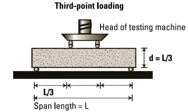
The bottom of the testing machine shall be equipped with two steel rollers, 38 mm in diameter, on which the specimen is to be kept, and these rollers shall be so arranged that the distance from centre to centre is 60 cm for 15.0 cm specimens or 40 cm for 10.0 cm specimens.
The load must be put in through two identical rollers arranged at the third point of the supporting span which is kept at 20 or 13.3 cm centre to centre. The load shall be split equally between the two loading rollers, and all rollers shall be arranged in such a way that the load is laid axially and without involving the sample in any torsional stresses or restraints.

d. Procedure
1. Make ready the test sample by loading the concrete into the mould in 3 layers of roughly equal thickness. Tamp each layer 35 times with the help of the tamping bar. Tamping should be spread uniformly over the whole cross-section of the beam mould and throughout the depth of each layer.
2. Clean the bearing surfaces of the supporting and loading rollers, and clear any loose sand or other material from the surfaces of the specimen where they are to make a connection with the rollers.
3. Circular rollers manufactured out of steel having cross-sections with a diameter of 38 mm will be utilized for offering support and loading points to the samples. The span of the rollers shall be a minimum of 10 mm more than the width of the test sample.
Four rollers shall be utilized, three out of which shall be qualified for rotation across their axes. The space between the outer rollers (i.e. span) must be 3d and the space between the inner rollers must be d.
The inner rollers shall be uniformly spaced between the outer rollers, such that the whole system is organised.
4. The sample kept in water shall be tested instantly on removal from water; whilst they are still wet. The test specimen shall be positioned in the machine precisely centred with the longitudinal axis of the specimen at right angles to the rollers.
For moulded samples, the mould filling direction must be normal to the direction of loading. The load shall be given at a rate of loading of 400 kg/min for the 15.0 cm specimens and a pace of 180 kg/min for the 10.0 cm samples.
d. Calculation
The Flexural Strength or modulus of rupture (fb) is given by
| fb = pl/bd2 |
(when a > 20 cm for 15 cm specimen or > 13 cm for 10 cm specimen) or
| fb = 3pa/bd2 |
(when a < 20 cm but > 17.0 for 15 cm sample or < 13.3 cm but > 11 cm for 10.0cm sample.)
Where,
a = the distance between the line of fracture and the nearer support, measured on the centre line of the tensile side of the sample.
b = width of specimen (cm)
d = failure point depth (cm)
l = supported length (cm)
p = max. Load (kg)
e. Conclusion
The Flexural strength of the concrete is noted to be two important figures.
f. Precautions
The precautions that need to be considered are as follows:
a. Have hand gloves, and safety shoes at the time of the test.
b. After the test turn off the machine.
c.Apply grease to all the exposed metal parts.
d. Maintain the guide rods firmly set to the base & top plate.
e. Equipment should be cleaned entirely before testing & after testing.
| Read Also: Road Construction Safety Tips |