Table of Contents
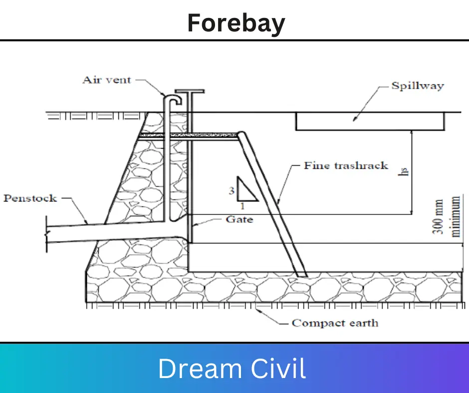
In this article, we will discuss forebay.
| Summary The structure located at the beginning of the penstock pressure shaft satisfying the function of supplying required flow to the turbine during start-up accommodates the rejected flow during shutdown and reduces the water hammer effect is called Forebay. When the conveyance system is a canal or low-pressure pipeline alignment, a Forebay is constructed between the conveyance system and the penstock pipe. |
1. Functions of Forebay
The Forebay of a hydropower scheme serves the following functions:
a. It allows for the transition from the open channel (Canal or low-pressure pipe flow) to pressure flow conditions.
b. It regulates the flow into the penstock, particularly through the release of excess water into a spillway.
c. It releases the surge pressure as the wave travels out of the penstock pipe.
d. It can also serve as a secondary/final settling basin and trap some particles that enter the headrace downstream of the settling basin.
e. The Forebay can also provide water storage for use during peak power demand periods (Sometimes balancing reservoir is constructed with Forebay to reserve water to meet the peak demand).
Structurally, the Forebay tank is similar to the settling basin except that the outlet transition is replaced by a trash rack and the entrance into the penstock pipe.
2. Components of Forebay
a. Derivation canal/pipe
b. Preparing gate
c. Trash rack
d. Forebay
e. Spillway and spillway canal
f. Emergency /repairing gate
g. Penstock
h. Air vent
i. Flushing for accumulation sediments
3. Design of Forebay
If the length of the headrace canal between the settling basin and the Forebay is long, then sediment can enter the canal, such as when debris fails from uphill of the headrace alignment Similarly if an earth canal (or stone masonry in mud mortar) is constructed between the settling basin and the Forebay, sometimes high velocity in the canal, such as running the monsoon can causes erosion and carries sediment to the Forebay.
In such cases, the Forebay should also be designed to serve as a secondary settling basin and the design method used for sizing a settling basin should be used. However. a lower sediment concentration (say C = 0 5 kg/m3) can be used since only particles that have escaped the settling basin or those that have been eroded from the headrace canal are expected in the Forebay.
If the headrace upstream of the Forebay consists of pipe or of cement masonry canal and the settling basin is functioning well, there will not be any need for secondary settling. However, as a precaution, some storage depth below the pipe invert should be allowed for this purpose.

4. Forebay Size
The volume of surge tank Vol = Qf X t X 60 m3
Where t is in a minute.
If possible, the Forebay should also be sized such that 2 to 3 minutes of the i design flow can be safely stored in the tank above the minimum pipe submergence level, and Qf is the Forebay discharge in m/sec.

The Forebay discharge is taken two times as the turbine (design) discharge (2Qd) because, during the closing of the valve, there will be backflow occurring from the penstock and the discharge from the conveyance system also continue for short time. Adopt suitable depth of water and velocity of flow (Limiting velocity 0.2m/sec to 0.8m/sec).
Q= bxhxV
Where V is the horizontal velocity of flow in the forebay
So, the depth of the basin h= Q/(V x b)
Read Also: Charpy Test

