Table of Contents
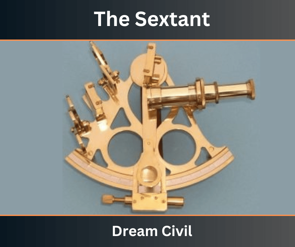
The distinguishing feature of the sextant is the arrangement of mirrors which enables the observer to sight two different objects simultaneously, and thus to measure the horizontal angle in a single observation.
A sextant may be used to measure the horizontal angle. It can also be used to measure the vertical angles.
Essentially, therefore, a sextant of fixed glass (H) is silvered to half the height while the upper half is plain.
Another glass (P) is attached to a movable arm which is operated by means of a milled head. The movable arm also carries a vernier at the other end.

The operation of the sextant depends on bringing the image of one point (R), after suitable reflection in two mirrors, into contact with the image of a second point (L) which is viewed directly, by moving the movable mirror (P).
Since the vernier and the movable mirror are attached to the same arm, the movement of the vernier from the zero position gives the required angle subtended by the two objects at the instrument station.
The sextant is based on the principle that when a ray of light is reflected successively from two mirrors, the angle between the first and last directions of the ray is twice the angle between the planes of the two mirrors.
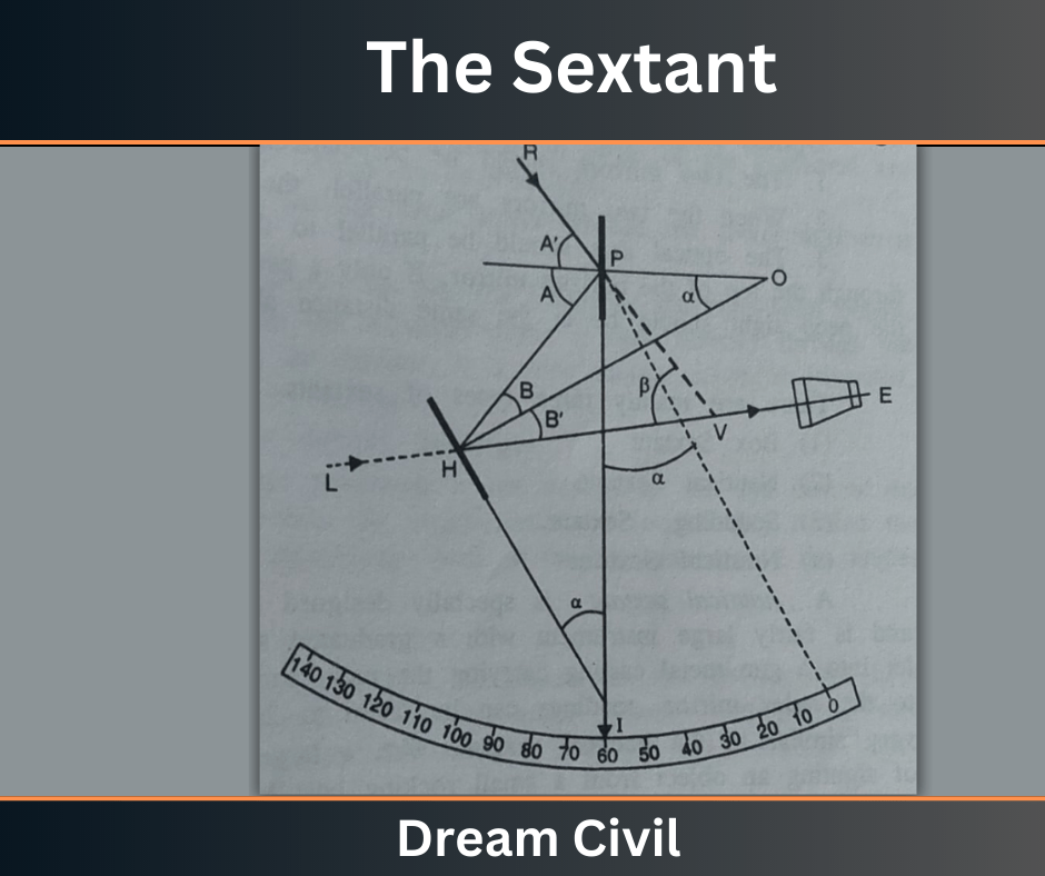
H is the fixed glass (also known as the horizon glass) and P is the index glass or the movable glass.
Let the angle between the planes of two glasses be α when the image of object R has been, after double reflection, brought in the same vertical line as that of object L viewed directly through the unsilvered portion of the glass H.

Fig: Optical Diagram of Sextant
Let the rays from both the objects subtend an angle β. PI is the index Pivoted at P. Since the angle of incidence is equal to the angle of reflection, we have
∠A = A’ ; ∠B =∠B’
α = ∠A — ∠B (exterior angle)
or
β = ∠A + ∠ A’ — (∠B + ∠B’) = 2∠A — 2∠B
β=2(∠ A – ∠B)
β=2α
Hence the angle between the mirrors is equal to half the actual angle between two objects. While constructing the sextant, the plane of mirror p is so adjusted that it is parallel to mirror H when the index reads zero.
The movement of the mirror P is equal to the movement of the vernier.
The scale is numbered in values equal to twice the actual angle so that the actual angle between the objects is read directly.
1. Optical Requirements of The Sextant
1. The two mirrors should be perpendicular to the plane of the graduated arc.
2. When the two mirrors are parallel, the reading on the index should be zero.
3. The optical axis should be parallel to the plane of the graduated arc and pass through the top of the horizon mirror.
If only a peep sight is provided in place of the telescope, the peep sight should be at the same distance above the arc as the top of the mirror.
2. Types of Sextant
There are mainly three types of sextants:
1. Nautical Sextant
2. Box Sextant
3. Sounding Sextant
a. Nautical Sextant
A nautical sextant is specially designed for navigation and astronomical purposes. It is a fairly large instrument with a graduated silver arc of about 15 to 20 cm radius let into a gunmetal casting carrying the main parts.
With the help of the vernier attached to the index mirror, readings can be taken to 20″ or 10″.
b. Box Sextant
The box sextant is a small pocket instrument used for measuring horizontal and vertical angles, measuring chain angles, and locating inaccessible points.
By setting the vernier to 90º, it may be used as an optical square.
A box sextant consists of the following parts:
(1) A circular box about 8 cm in diameter and 4 cm high.
(2) A fixed horizon glass, silvered at the lower half and plain at the upper half.
(3) A movable index glass fully silvered.
(4) An index arm pivoted at the index glass and carried a vernier at the other end.
(5) An adjustable magnifying glass, to read the angle.
(6) A milled-headed screw to rotate the index glass and the index arm.
(7) An eyehole or peephole or a telescope for long-distance sighting,
(8) A pair of colored glasses lOr use in bright sun.
(9) A slot in the side of the box for the object to be sighted.
3. Measurement of Horizontal Angle with Box Sextant
1. Hold the instrument in the right hand and bring the plane of the graduated arc into the plane of the eye and the two points to be observed.
2. Look through the eyehole at the left-hand object through the lower unsilvered of the horizon glass.
3. Turn the milled-headed screw slowly so that the image of the right-hand Object, double reflection, is coincident with the left-hand object; view directly through the upper half of the horizon glass. Clamp the vernier. If a slow-motion screw is provided, bring the images of an object into exact coincidence.
The reading on the vernier gives directly the angle.
Note:
The vertex (V) of an angle measured is not exactly at the eye but at the intersection of the two lines of sight which, for small angles, is considerably behind the eye.
For this reason, there may be an appreciable error in the measurement of the angles less than, say, 15°.
4. Measurement of Vertical Angle with Sextant
Vertical angles may be measured by holding the sextant so that its arc lies in a vertical plane.
If it is required to measure the vertical angle between two points, view the lower object directly, and turn the milled-headed screw until the image of the higher object appears coincident with the lower one.
5. Permanent Adjustment of a Sextant
A sextant requires the following four adjustments:
(1) To make the index glass perpendicular to the plane of the graduated arc.
(2) To make the horizon glass perpendicular to the plane of the graduated arc.
(3) To make the line of sight parallel to the plane of the graduated arc.
(4) To make the horizon mirror parallel to the index mirror when the vernier is set at zero (i.e. to eliminate an index correction).
In a box sextant, the index glass is permanently fixed at right angles to the plane of the instrument by the maker. Also, no provision is made for adjustment 3.
Hence, only adjustments 2 and 4 are made for a box sextant.
a. Adjustment 2: Adjustment of the Horizon Glass
(i) Set the vernier at approximately zero and aim at some well-defined distant point like a star, with the arc vertical.
(ii) Move the index arm back and forth slightly. The image of the star will move up and down.
(iii) Adjust the horizon mirror by tilting it forward or backward until, when the index arm is moved, the image of the star, in passing will coincide with the star itself.
b. Adjustment 4: Elimination of index error
(i) Bring the direct and reflected image of a distant joint into coincidence. If the vernier doesn’t zero, the error is called the index error.
(ii) Correct the error by turning the horizontal glass around an axis perpendicular to the plane of the graduated arc.
If the index error is not significant, it is customary not to correct the error, but to apply the correction to the observed readings. An index error should, however, be determined from time to time.
6. References1. Content Filter & Authenticity Checking Team, Dream Civil International (Our team checks every content & detail to maintain quality.) |
Read More: De Lisles Clinometer

